
If the pitch centre distance and number of teeth on both driving and driven sprockets are known, you can use the following formula, tables and charts to calculate chain lengths.
If shock loads are expected, then first determine the class of load on the basis of the drives equipment ( see table 1). Note : If table 1 does not list your equipment, go by its similarity to a listed item 89
| Lubricant | TABLE 1 |
|---|
| UNIFORM LOAD | MODERATE SHOCK LOAD | HEAVY SHOCK LOAD |
|---|---|---|
| Centrifugal pumps, Agitator for liquids, Conveyors, Fans-Uniform load Generators, M/c’s all types with uniformnon - reversing loads |
Reciprocating pumps, Wood working M/c'sGrinders, Conveyors-Irregular load Mixers and Machinesall types with moderateshock and non-reversing loads |
Presses, Earthmoving equipment Shears, Cranes & Hoists, Reciprocating and Shaker typeconveyors, Crushers, Reciprocating feeders Machines-all types with severe impactshock loads orvariation andreversing service |
Note : If table 1 does not list your equipment, go by its similarity to a listed item
Establish the design horsepower by multiplying the specified horsepower value with the service factor given in Table 2.
| LOAD CLASSIFICATIONS | TABLE 1 |
|---|
| TYPE OF DRIVEN LOAD | TYPE OF INPUT POWER | ||
|---|---|---|---|
| Uniform Moderate Shock Heavy Shock | Internal Combustion Engine with Hydraulic Drive 1.0 1.2 1.4 |
Electric Motor or Turbine 1.0 1.3 1.5 |
Internal Combustion Engine with Mechanical Drive 1.2 1.4 1.7 |
Selection of multi- strand chains will become necessary if available space is limited or high speeds call for a chain with lower pitch .
The strand factors are given in Table 3. To facilitate selection of multistrand chains, multiply the horsepower rating for single strand chains by the corresponding strand factor.
ISO 10823 - 1996 standard of guidance can be referred for selection of chain drive power.
Actual power = Input power x service factor x strand factor. Considering the actual power and rpm of the pinion, using the horsepower rating chart select the chain for the application.
By using the required shaft speed ratio select the number of teeth in the large sprocket. If the required shaft speed ratio cannot be obtained with a standard sprocket, increase the number of teeth in the small sprocket by one or two, to obtain an acceptable speed ratio with a slightly larger standard sprocket. The size of the large sprocket is affected by the allowable wear elongation of the chain which may go up to 3 %. The use of sprockets with more than 67 teeth reduces the life of the chain expressed in percentageelongation as :
Permissible wear elongation = 200 / N ( %). The speed ratio for a single drive should be not exceed 10:1
A greater ratio will make it necessary to provide for two drives in series
Compute the length of chain required using the formula given below. If possible, adjust the centre distance, so that the length of chain required is always in an even number of pitches. For optimum life of the chain and sprockets the centre distance between the two sprockets should be 30 to 50 times the chain pitch.
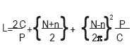
Where L= Chain length in pitches
P= Chain Pitch
C= Contemplated centre distance
N= Number of teeth on large sprocket
N= Number of teeth on small sprocket